The purpose of this post is to describe the relevant theory needed to understand the paper “High signal to noise absorption imaging of alkali atoms at moderate
magnetic fields” by Hans et al. In particular, a key paper which they cite that details the calibration of the absorption imaging setup is “Strong saturation absorption imaging of dense clouds of ultracold atoms” by Reinaudi et al. Another useful resource is the PhD dissertation of Hans which goes into more depth on details that are omitted in their paper.
Atomic Structure of \(^{39}\text K\)
The alkali atom isotope \(^{39}\text K\) has fixed, non-negotiable electron spin \(s=1/2\) and nuclear spin \(i=3/2\); hence it is bosonic \(s+i=2\). Within the gross \(n\)-manifold for \(n=4\), consider either the \(4s_{1/2}\) or \(4p_{1/2}\) fine \(j\)-manifolds for \(j=1/2\). In both cases, there are two hyperfine \(f\)-manifolds corresponding to total atomic angular momenta \(f=1,2\). In the strict absence \(\textbf B=\textbf 0\) of an external magnetic field, the \(f=1\) hyperfine manifold has \(3\) degenerate \(m_f\)-sublevels corresponding to projections \(m_f=-1,0,1\) of the total atomic angular momentum along some arbitrary \(z\)-axis, while the \(f=2\) hyperfine manifold has \(5\) degenerate \(m_f\)-sublevels corresponding to \(m_f=-2,-1,0,1,2\). However, upon turning \(\textbf B\neq\textbf 0\) on with \(B:=|\textbf B|\), the Breit-Rabi formula asserts that the \(2f+1\)-fold degeneracy among the Zeeman sublevels within each hyperfine \(f\)-manifold is lifted exactly according to the trajectories:
\[\Delta E_{|f=3/2\pm 1/2,m_f\rangle}(B)=-\frac{A}{4}\pm\frac{1}{2}\sqrt{4A^2+2m_fAg_j\mu_BB+(g_j\mu_BB)^2}\]
where \(g_j=2\) for \(4s_{1/2}\) and \(g_j=2/3\) for \(4p_{1/2}\), and \(A\approx h\times 230.859860\text{ MHz}\) for \(4s_{1/2}\) whereas \(A\approx h\times 27.793\text{ MHz}\) for \(4p_{1/2}\) (see the data for \(^{39}\text K\) here).
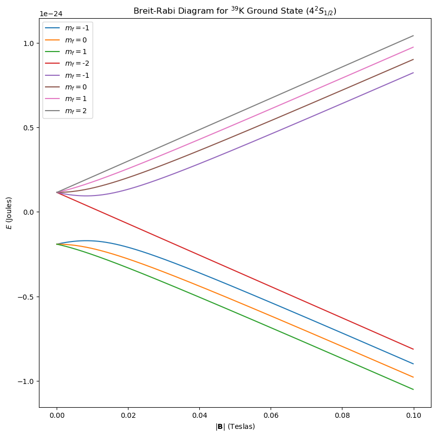
- Intuitively, the reason why the \(m_f\) sublevels seem to be inverted in the \(4s_{1/2}\), \(f=1\) hyperfine manifold is that \(g_f=-1/2<0\) is negative and to first-order the Zeeman perturbation is \(g_fm_f\mu_BB\) (originally \(-\boldsymbol{\mu}\cdot\textbf B\) but \(q=-e\)).
- 2D scan of \(I_{\sigma^+}+I_{\sigma^-}\) vs. \(I_{\sigma^+}/I_{\sigma^-}\), in an ideal world the measured OD should be constant across the entire space (as measured at low-field), but
- AOM driver right now is just being controlled by essentially varying a potentiometer \(R_2\) which controls the voltage at the midpoint of a voltage divider, which is fed into a voltage oscillator circuit that effectively maps \(V\to\omega_{\text{ext}}\) to RF-drive the AOM with. By flicking the switch, voltage divider circuit is no longer controlling it, instead it’s externally controlled by a computer in the Cicero Word Generator GUI for AMO physics experiments.
- The natural line width of optical/visible light (THz) transitions is practically zero compared with the RF transition (on the order of 400 MHz) between potassium-39 hyperfine states because \(\Gamma\propto\omega_{01}^3\).
- Need to first lock onto the right B-field (395 G) by doing a frequency sweep. Then, once that is locked onto, need to then impose correct frequency shifts on the AOMs (have a substantial line width/leeway here like 6 MHz or something?), will require a second frequency sweep to find max SNR) centered around roughly where we expect it to be located anyways (show calculation for this).
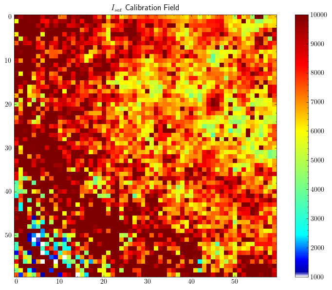
- Panos’s thesis did pixel-by-pixel calibration.
- https://www.tobiastiecke.nl/archive/PotassiumProperties.pdf
- Description of the experiment:
- The idea is that one would like to do spin-resolved polaron injection spectroscopy.
- D\(1\) repump light is from \(4s_{1/2}\) manifold (typically use \(|1,1\rangle\) for its broad Feshbach resonance) to \(4p_{1/2}\) manifold \(|2,2\rangle\). D\(2\) imaging light is from \(4s_{1/2}\) to \(4p_{3/2}\) stretched state \(|3,3\rangle\).
- The D\(2\) laser light is first incident on a \(\lambda/2\) waveplate which rotates the polarizations so that some go into each arm of a double-pass AOM. It is first passed into an AOM double-pass setup to get \(\pm 220\text{ MHz}\). These then are incident on a D\(2\) flip mirror which redirects this D\(2\) light into the modular optical breadboard setup we built. Specifically, the crossed polarizations are incident on a \(\lambda/2\) waveplate that rotates a certain amount of polarization into each of two double-pass AOM arms. One branch is additive by \(220\text{ MHz}\) in total (after double-pass) while the other branch is subtractive \(-220\text{ MHz}\), so when aligning it is essential to maximize the correct order \(m=\pm 1\), and to check this by turning on the TTL switch of the driver to see which order is left just before the iris. These then need to be overlapped onto an output fiber, with another \(\lambda/2\) waveplate onto a PBS which will throw away \(P/2\) but at the benefit of having a single polarization propagating through your polarization-maintaining fiber and directly into the science cell. This waveplate also allows optimizing \(I_{\sigma^+}/I_{\sigma^-}\).
- The AOM drivers are controlled by a digital channel for using Cicero to do TTL switching and also an analog channel for using Cicero to change driving amplitude of the AOMs (Janet for the \(-220\text{ MHz}\) and Billy for \(+220\text{ MHz}\)). In Cicero, the Override option for the D\(2\) flip mirror needs to be checked, but value is off for it to be down. Also, when overriding a digital channel, it is automatic, but when overriding an analog channel, need to specifically say so.
- If one wishes to abort a given sequence, best to tick the box, and when the sequence is finished (usually around \(30\) seconds). to quickly close it and click “restart sequence” to start up a new sequence or something (to keep coils heated).
- There are quadrupole coils (seem like 4 pairs?) in an anti-Helmholtz configuration for the MOT, Feshbach coils for the broad \(|1,1\rangle\) Feshbach resonance field to tune \(a\) (there are some empirical correlations in Cicero between the applied voltage in the coils and the corresponding \(B\to a\) you get out of it).
- Optical dipole trap (ODT), the light for that is the dangerous IR (power is 1 Watt, can even burn your skin).
- “Walking the beam” (draw schematic) by turning say \(\phi_1\) and seeing which direction \(\phi_2\) needs to go to keep at the same voltage, doing same for \(\theta_1,\theta_2\)…adjusting collimation at the end.
- Fiber pen, fiber cleaning kit (microscope, never look into it if the other end of fiber is coupled to light or will go blind).
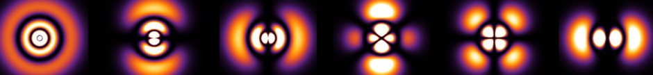
- To actually make the optical box trap of green light, shine light onto a spatial light modulator (SLM, which is a bunch of liquid crystals applying some phase and stuff, a Freedericksz transition?, a bit like DMD except rotates slower so response time is kinda ass). Box is not a perfect cylinder, it is more like the waist of a Gaussian beam (length of \(40\) microns or so is Rayleigh distance \(z_R\)), and the sides are given by steep power law potentials. A bunch of lenses of various \(f\) act like Fourier transformers, etc. so that light field at focal plane is Fraunhofer pattern of SLM grating.
- When locking onto say the D\(2\) laser, have an absorption cell of solid \(\text K(s)\) with melting point around \(40^{\circ}\text{ C}\). Doppler-free spectroscopy allows measuring . derivative is physically measured, two PID controllers for different time scales used to